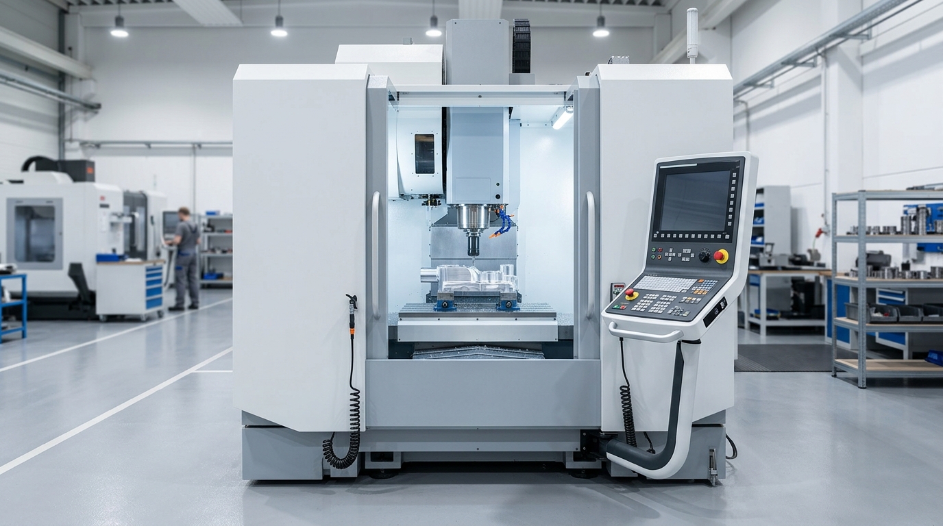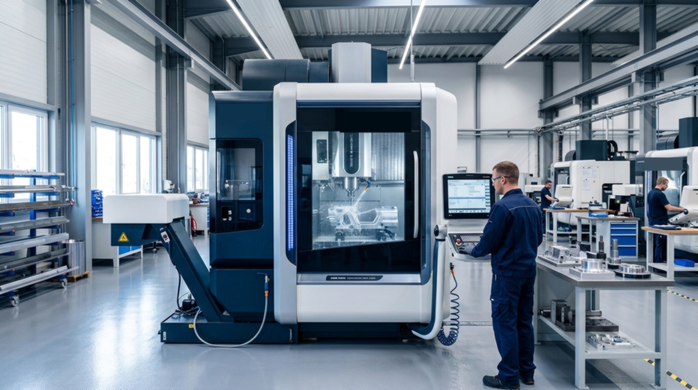
- The 6-Step Workflow: Operating a CNC follows a disciplined sequence: CAD Model → CAM Toolpaths → Workpiece Clamping → Tool Offsets → Dry Run Verification → Live Machining.
- Work Coordinate System (G54): The operator must establish the physical relationship between the part origin (X0 Y0 Z0) and machine coordinates using edge finders or touch probes.
- Tool Length Compensation (H Offset): Every cutting tool has a unique length that must be registered in the controller to prevent catastrophic spindle crashes.
- Safety First: Never operate without safety glasses, maintain interlock door enclosures, and always perform an "air cut" dry run when executing a new program.
What is a CNC Machine Operator?
Before learning how to use a CNC machine, it is important to understand the role of a CNC Machine Operator.
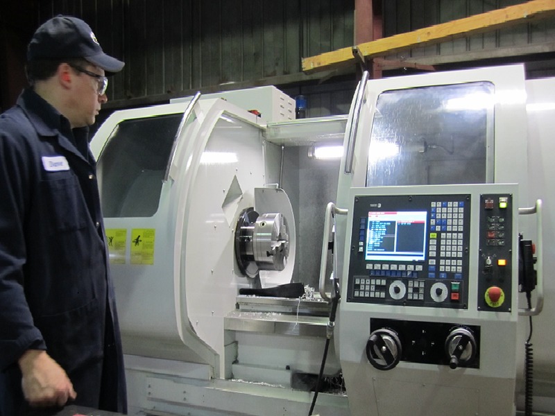
A CNC machine operator is a skilled technician responsible for setting up machine tools, loading raw materials into chucks or vises, downloading G-code programs, verifying tool offsets, monitoring cutting conditions (sound, vibration, chip formation), and inspecting finished parts using precision metrology tools like micrometers and bore gauges.
The 6-Phase CNC Operating Workflow
Executing a successful CNC machining job involves six sequential engineering phases:
Phase 1: CAD 3D Modeling & Design for Manufacturability
The process begins in 3D CAD software (SolidWorks, Inventor, Fusion 360). Ensure part features can be accessed by standard cutting tools, avoid excessively deep pockets (keep pocket depth under 4× tool diameter), and provide standard inside corner radii.
Phase 2: CAM Programming & Toolpath Strategy
In CAM software, the programmer defines:
- Workpiece stock dimensions.
- Coordinate system orientation (Z-axis pointing up out of the part).
- Cutting tool types (e.g., Ø50 mm face mill, Ø12 mm roughing end mill, Ø6 mm ball end mill, M6 tap).
- Spindle speeds (RPM) and feed rates (mm/min).
- Post-processing into the controller-specific G-code file (
.NCor.TAP).
Phase 3: Workpiece Clamping & Machine Table Setup
Secure the metal stock inside the machine enclosure:
- Clean Surfaces: Stone the machine table and vise jaws to remove chips, burrs, and grit.
- Clamping: Clamp the workpiece in a precision machine vise using ground parallels, or bolt down fixtures with T-slot clamps.
- Squaring: Run a dial test indicator along the fixed vise jaw to ensure alignment within 0.01 mm of the X-axis travel.
Phase 4: Setting Work Coordinates (G54) & Tool Length Offsets (H)
The machine must know where the part is located in 3D physical space:
- X and Y Offsets (G54): Use a mechanical edge finder, laser finder, or 3D touch probe (such as Renishaw) to touch the part edges. Enter the center coordinates into the G54 Work Coordinate System.
- Z-Axis Part Zero: Touch the tool tip to the top finished surface of the part and register
Z0. - Tool Length Offsets (H1, H2, H3...): Measure the gauge length of every tool loaded in the magazine using an optical tool setter or contact touch-plate, recording heights in the tool geometry table.
Phase 5: The "Dry Run" & Air Cutting Verification
- Shift the Z-axis coordinate up by +50 mm or +100 mm in G54.
- Turn on Single Block Mode (
SBL) and reduce Rapid Feedrate Override to 25%. - Press Cycle Start, inspecting the "Distance-To-Go" display on the screen at every step to verify the tool will not collide with the vise or clamps.
Phase 6: Automated Live Cycle & Part Inspection
- Reset the Z-coordinate back to zero.
- Turn on high-pressure flood coolant.
- Keep one hand resting near the Feed Hold button and Emergency Stop (E-Stop) button.
- Listen to the cutting acoustics: a steady cutting hum indicates proper chip load; high-pitched chatter or squealing indicates incorrect feeds, speeds, or dull tooling.
- After the cycle finishes, deburr the part and measure critical dimensions with calibrated digital calipers, micrometers, and height gauges.
The 7 Golden Safety Rules of CNC Machining
| Safety Rule | Requirement | Hazard Prevented |
|---|---|---|
| 1. Eye Protection | ANSI Z87.1 certified safety glasses at all times | Flying metal chips, broken tool shards, high-pressure coolant spray. |
| 2. No Gloves or Loose Attire | Tie back long hair; never wear gloves near rotating spindles | Entanglement in high-speed spinning shafts and cutter flutes. |
| 3. Interlock Enclosures | Keep safety doors fully closed during automatic cycle execution | Shields operator from ejected workpieces or shattered carbide cutters. |
| 4. Chuck Key Discipline | Never remove your hand from a manual lathe chuck key | Prevents chuck key from being launched like a projectile upon spindle start. |
| 5. Verify Distance-To-Go | Monitor remaining travel distance on the screen during rapid moves | Prevents catastrophic spindle crashes into vises, rotary tables, or raw stock. |
| 6. Clamp Tightness Check | Verify hydraulic pressure gauge and torque all vise handles securely | Stops stock from being torn out of clamping jaws under heavy roughing loads. |
| 7. Chip Clearing Tools | Use chip brushes and brass hooks; never use bare fingers | Avoids severe lacerations from razor-sharp steel and stainless spiral chips. |
Frequently Asked Questions
What is the most common mistake made by new CNC operators?
Setting an incorrect Tool Length Offset (H) or confusing the Z-axis coordinate sign. If the controller believes a tool is 50 mm shorter than its true physical length, the spindle will plunge directly into the workpiece at full rapid speed. Always check the distance-to-go on rapid approaches!
How long does it take to learn how to use a CNC machine?
Basic machine operation (loading parts, setting tool offsets, running pre-verified G-code) can be mastered in 2 to 4 weeks. Full CAM programming, complex multi-axis setup, and independent troubleshooting typically require 6 to 12 months of hands-on shopfloor experience.
What is G54 in CNC programming?
G54 is the default Work Coordinate System (WCS) command. It instructs the CNC controller to offset all program X, Y, and Z movements relative to a user-defined physical zero point on the clamped workpiece rather than the machine's home reference switches.