- CNC stands for Computer Numerical Control: an automated manufacturing technology where computer software directs cutting tools along multi-axis trajectories.
- Unrivaled Repeatability: CNC machine tools achieve mechanical positioning accuracies within ±0.005 mm (5 microns), replacing manual handwheels.
- Major Configurations: Primary types include Vertical Machining Centers (VMC), CNC Turning Lathes, 5-Axis Machining Centers, Heavy Gantry Mills, and CNC Routers.
- Core Architecture: Composed of a rigid meehanite cast-iron bed, high-torque spindle, precision linear roller guideways, servo motors, and an industrial CNC controller (FANUC, Siemens, or Syntec).
What Does CNC Machine Stand For?
To understand what is a CNC machine, one must first understand its acronym: CNC stands for Computer Numerical Control.
In conventional machine tools, a machinist manually turned handwheels, pulled clutch levers, and inspected dials to move cutting cutters against metal stock. In a CNC machine, an onboard industrial computer computerizes this entire process. Digital blueprints designed in CAD (Computer-Aided Design) software are translated into mathematical coordinate paths (G-code) by CAM (Computer-Aided Manufacturing) software. The CNC controller executes these coordinates with micro-inch accuracy, directing high-torque brushless servo motors to move axes simultaneously.
How Does a CNC Machine Work?
The operational chain of Computer Numerical Control follows an automated closed-loop feedback workflow:
- Digital Design (CAD): An engineer models a physical part in 3D CAD software (such as SolidWorks, Autodesk Fusion, or Siemens NX).
- Toolpath Generation (CAM): The CAM system analyzes workpiece geometry, selecting appropriate cutting tools (end mills, drills, face mills) and calculating optimal feeds, speeds, and tool trajectories.
- G-Code Post-Processing: The CAM file is converted into standardized alphanumeric commands (G-codes and M-codes) compatible with the machine's specific controller.
- Controller Execution: The machine's CNC controller decodes G-code blocks in real-time, sending frequency pulse trains to digital servo drives.
- Servo Motor & Ballscrew Translation: AC brushless servo motors rotate precision ground C3 ballscrews, translating rotational torque into linear axis travel along X, Y, and Z axes.
- Closed-Loop Feedback: Optical linear glass scales and absolute encoders monitor axis positions continuously, feeding back coordinates at sub-micron resolution to eliminate backlash and thermal drift.
Core Anatomical Components of an Industrial CNC Machine
Every high-precision CNC machine tool relies on six foundational engineering assemblies:
| Subsystem | Typical Specifications | Functional Purpose |
|---|---|---|
| Heavy Machine Bed & Column | HT300 / Meehanite resin-sand casting | Absorbs cutting vibrations, maintains geometric alignment under heavy cutting forces. |
| Spindle Unit | BT40 / BT50 / HSK-A63 (8,000–15,000 RPM) | Rotates cutting tools or stock at high speed with ultra-low radial runout (<0.003 mm). |
| Guideway System | Roller linear guideways or hardened box ways | Constrains axis travel along straight trajectories with minimal friction and zero stick-slip. |
| CNC Controller Unit | FANUC 0i-MF Plus, Siemens 828D, Syntec 22MA | The "brain" that calculates trajectory interpolation, tool offsets, and safety interlocks. |
| Automatic Tool Changer (ATC) | 16-tool carousel or 24-tool twin-arm magazine | Swaps cutting tools automatically in 1.5 to 2.5 seconds without operator intervention. |
| Coolant & Chip Evacuation | High-pressure flood & 20-bar Through-Spindle (CTS) | Flushes metal chips away from cutting zone, cools carbide inserts, and extends tool life. |
The Primary Classifications of CNC Machines
Depending on workpiece geometry and kinematics, CNC machine tools are categorized into distinct configurations:
1. Vertical Machining Centers (VMC)
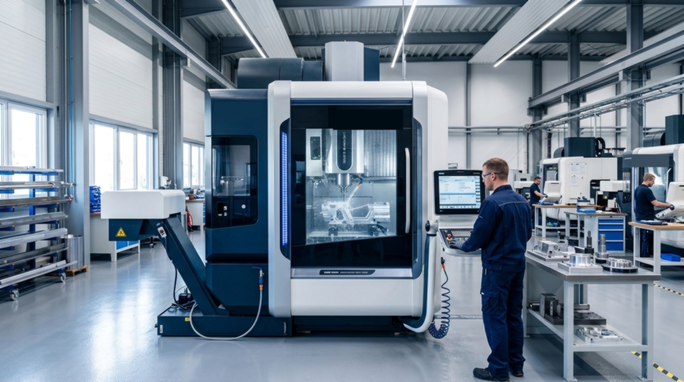
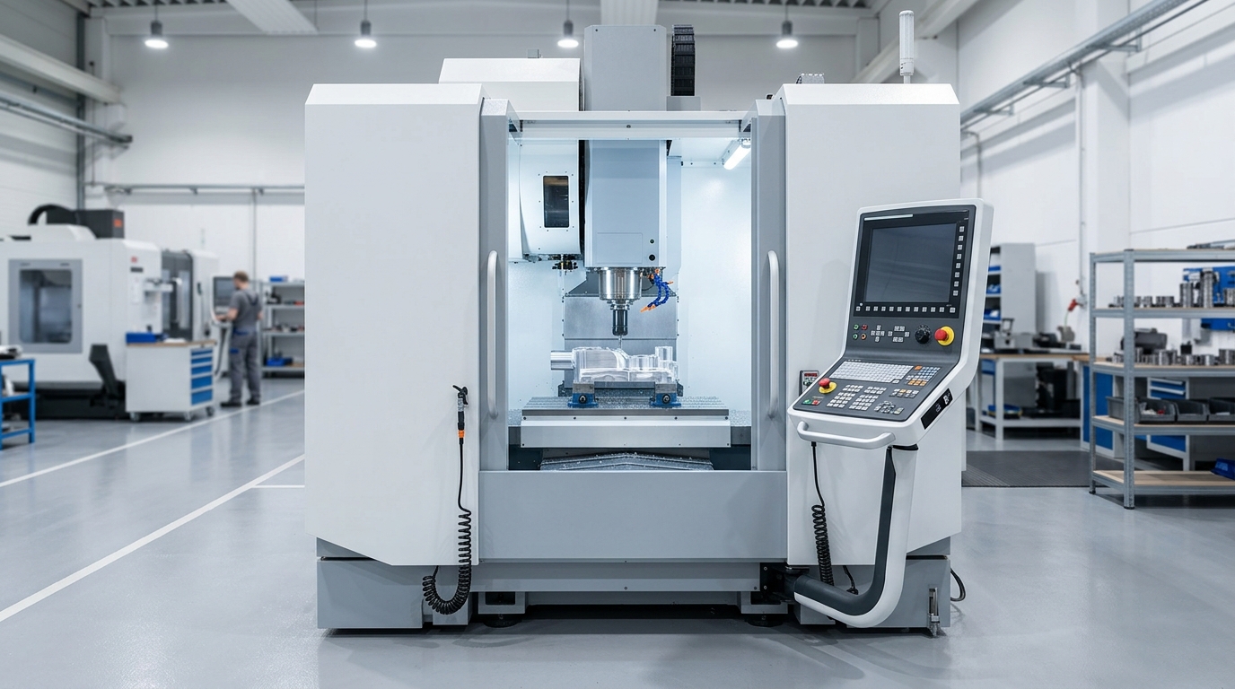
The industry workhorse. In a VMC, the spindle is oriented vertically, cutting parts secured to a horizontal reciprocating worktable. Standard models like the VMC 850 and compact VMC 650 handle 3-axis milling, drilling, slotting, tapping, and mold cavity machining.
2. CNC Lathes & Turning Centers
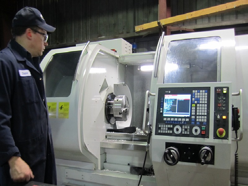
In CNC lathes, the workpiece is clamped in a rotating hydraulic chuck while stationary cutting inserts travel along X (diameter) and Z (length) axes to turn round parts, shafts, flanges, and threads. Slant bed lathes feature a 30° or 45° angled casting that uses gravity to discharge chips effortlessly.
3. 5-Axis Machining Centers
Advanced centers that add two rotary axes (A and C, or B and C) to the standard X, Y, and Z linear axes. This permits the cutting tool to approach a workpiece from virtually any orientation in a single clamping setup, essential for aerospace impellers, turbine blades, and orthopedic implants.
4. Gantry & Double-Column Machining Centers
Heavyweight industrial giants featuring a bridge-like portal structure spanning over a stationary worktable. Designed for massive dies, aerospace wing spars, railway bogies, and automotive stamping tool tooling.
5. CNC Routers vs. CNC Mills
While CNC mills cut heavy metals (steel, titanium, cast iron) at lower RPMs with extreme rigidity, CNC routers are designed for softer materials (wood, plastics, composites, aluminum sheet) with larger cutting envelopes and high-speed spindles (18,000–24,000 RPM).
Frequently Asked Questions
What does CNC stand for in machining?
CNC stands for Computer Numerical Control. In machining terminology, it refers to the automated control of machining tools (such as drills, boring tools, and lathes) via a programmable onboard computer executing G-code instructions.
What is the difference between a conventional machine and a CNC machine?
A conventional manual machine requires the machinist to guide cutting tools by hand, relying on visual inspection and tactile feedback. A CNC machine executes automated code commands with servo motor accuracy, producing hundreds of identical parts with tolerances as fine as ±0.005 mm without operator fatigue.
Can a beginner learn to operate a CNC machine?
Yes. Modern CNC controllers offer conversational programming interfaces, interactive graphical toolpath simulations, and automated touch-probes that make learning basic machine setup and operation approachable within a few weeks of structured technical training.